Trail Tracer:
The Trail Tracer adds self driving capabilities to any normal R/C vehicle, opening up an entirely new way to build, race, and play. Create your own courses, watch your car navigate on its own, and push your builds in ways never thought possible. It’s not just a new feature for RC cars, it’s a whole new hobby.
The Trail Tracer guides the vehicle along a wire loop that can be buried in the ground, or laid across the surface. The basic set is easy to install and gives the vehicle the ability to follow the wire autonomously, or in semi-manual ‘cruise control’ mode.
Automatic battery charging capabilities can be added with the addition of the Charge Port (CP) board, and a DIY charging station. Build plans/instructions can be found in the Advanced Setup Tutorial Video. This enables the vehicle to drive autonomously 24/7.
Additional capabilities such as multi-vehicle collision avoidance and automatic speed changes can be triggered with the addition of Beacon Transmitter (BTx) boards.

Software:
The Receiver Board uses an STM32 microcontroller for signal processing, and an ESP32-S2 microcontroller for everything else. The ESP32 code is open source so you can edit or add features as you wish.
How It Works:
The Transmitter Board generates a ~50 kHz sine wave signal in the wire loop. This oscillating current generates an electromagnetic field that can be sensed from a distance. There is a sensor comprised of two small coils of wire mounted on the front bumper of the vehicle. When these coils get near the wire loop, they start to pick up the oscillating electromagnetic field from the wire. The closer they get, the stronger the signal becomes. We can use this signal strength to caculate the distance from the wire.
This type of wire guidance technology is widely used in industrial automated vehicles, such as warehouse robots, which follow wire loops embedded in the floor. Similar technology is also used for perimeter or boundary wires in applications such as robotic lawn mowers and invisible pet fences.
The sensor contains two overlapping wire coils positioned 90° apart, in an X shape. As the electromagnetic field passes through the coils, it induces a small voltage in each one. These voltage signals are amplified, filtered, and processed by the onboard STM32 microcontroller. With some clever math, the microcontroller compares the relative signal strength from each coil to determine the X,Y position of the wire.
The greens and purple arrows represent the signal strength from each coil. The calculated distance is used by the steering controller to follow the wire.
A detailed description of how the Trail Tracer works can be found here
Features:
The Trail Tracers core function is to guide the vehicle along the wire, but we’ve added a few additional features that make it way more fun:
Semi-manual mode - vehicle attempts to follow the wire but you still have full control override via your R/C transmitter
Automatic mode - Can drive on it’s own without the use of an R/C controller
Automatic battery charging - requires the Charge Port board and a DIY charging dock
Wireless Telemetry - monitor the vehicle wirelessly from up to 200’ away with the addition of an ESP32 + display
Multi-vehicle collision avoidance - run multiple vehicles on the same trail. Add a BeaconTx to the rear bumper of each vehicle to prevent them from crashing into each other
Creep Throttle - add a BeaconTx anywhere along the trail to trigger automatic throttle changes
SineSwerve - offsets the steering controller set point in a slow moving sine wave pattern. This can reduce acute trail erosion by distributing tire tracks over a wider area
Rear steering and dual sensors - with the addition of a second sensor coil on the rear bumper, the vehicles heading relative to the wire can be measured. The heading can be used with the rear-steering controller for vehicles with steerable rear wheels, or it can be fed into the main steering controller for improved accuracy
Stuck detector - cuts the throttle if the distance from the wire stops changing over time. Useful for fully automated driving when unattended
Open Source ESP32 code - The Receiver board uses an ESP32-S2 with open source software. This enables users to add their own features or use the Trail Tracer for custom robotics applications
Required for use:
R/C car with ESC and Servo that use a standard PWM servo signal
20 AWG PVC Wire (or similar)
USB-C cable to power Tx Board, and 5V USB power source
Micro USB cable to connect Rx Board to PC or Mac
Charge system (optional) requires DIY construction of a charge port system (see advanced tutorial)
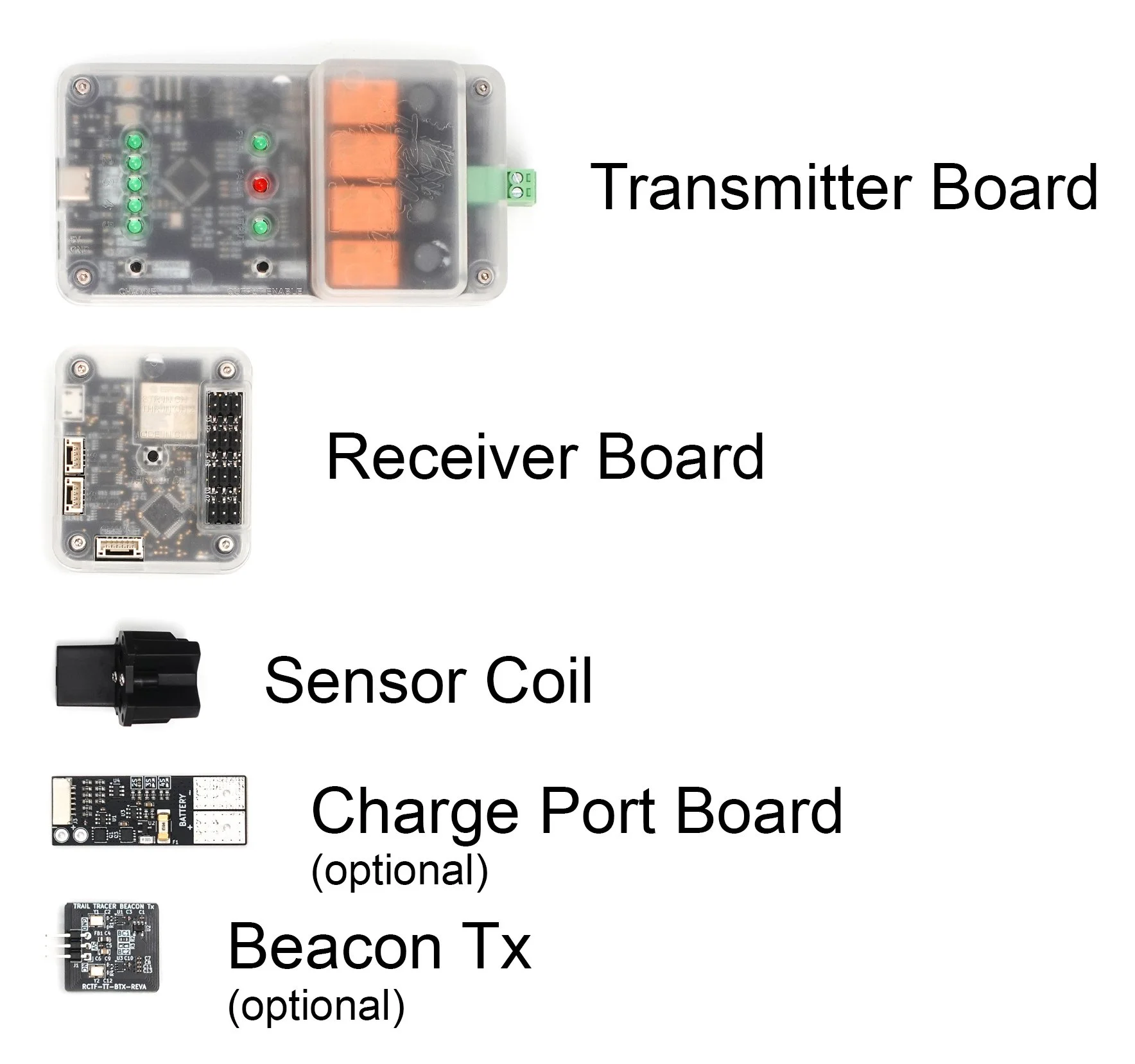
Component Description:
Transmitter Board: Generates the signal in the wire that the vehicle follows.
Receiver Board: The ‘brain’ of the vehicle. Reads the distance to the wire via the sensor coil and outputs the required steering servo signal to guide the vehicle along the wire. Controls throttle, and optionally reads R/C receiver outputs for manual control driving modes.
Sensor Coil: Contains two PCB wire coils that act as the ‘antennas’ that sense the wire signal.
Charge Port Board: Only used for automated charging control. Connects in-between the charge contacts and battery. Measures battery voltage and charge current for the Receiver Board to control charging.
Beacon Tx: Emits a signal on a different frequency than the Transmitter Board. The Receiver can detect this signal and use it to trigger various features like speed changes, sine-swerve mode, and multi-vehicle collision avoidance.